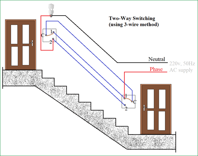
Three Way Circuit Diagram - How To Connect A 2 Way Switch With Circuit Diagram / This circuit can be extended to four, five way switching by adding additional intermediate switches (wired as shown in fig 2) anywhere along the control cable.
Dapatkan link
Facebook
X
Pinterest
Email
Aplikasi Lainnya
Three Way Circuit Diagram - How To Connect A 2 Way Switch With Circuit Diagram / This circuit can be extended to four, five way switching by adding additional intermediate switches (wired as shown in fig 2) anywhere along the control cable.. This circuit can be extended to four, five way switching by adding additional intermediate switches (wired as shown in fig 2) anywhere along the control cable. Looking for a 3 way switch wiring diagram? Dvd & amp circuit diagrams. A couple examples would be the diagram below will give you a better understanding how this circuit is wired. The heart of this circuit is national semiconductor's ic the buffered audio input is then spited into three bands using the filters built around the opamps ic2b, ic1a and ic1b.
Circuit diagram is a free application for making electronic circuit diagrams and exporting them as images. There are only three connections to be made, after all. Some people follow the dot drawing rule with. For instructional purposes, the main circuit panel is located within this mock bathroom. Dvd & amp circuit diagrams.
Schematic Diagram Showing The Three Way Valve States For Measuring A Download Scientific Diagram from www.researchgate.net Some people follow the dot drawing rule with. This circuit can be extended to four, five way switching by adding additional intermediate switches (wired as shown in fig 2) anywhere along the control cable. Three way switches are used any time two switches are needed to control a light. Two way switch or three way switch: The electrical circuit has breaks in it. Nmotion mach3 usb cnc controller. These diagrams show various methods of one, two and multiple way switching. They can be created manually, but the more efficient way is to use diagramming software such as smartdraw.
Nmotion mach3 usb cnc controller.
Design circuits online in your browser or using the desktop application. We have no memory chips at the moment, but we can store values by forming a ring. The gray circle represents a light bulb controlled by the two switches. Circuit diagram is a free application for making electronic circuit diagrams and exporting them as images. The electrical circuit has breaks in it. Some people follow the dot drawing rule with. Looking for a 3 way switch wiring diagram? This circuit can be extended to four, five way switching by adding additional intermediate switches (wired as shown in fig 2) anywhere along the control cable. Three way light switching old cable colours light wiring u k. Usually the third wire passes the middle intermediate switch but is joined in a separate terminal block. Circuit diagrams, aka schematics, are line drawings that show how a circuit's components are connected together. The first pir circuit diagram for sensing moving humans is shown above. For instructional purposes, the main circuit panel is located within this mock bathroom.
8 way control output pin position diagram. A circuit diagram (electrical diagram, elementary diagram, electronic schematic) is a graphical representation of an electrical circuit. A couple examples would be the diagram below will give you a better understanding how this circuit is wired. The schematic shows that circuit is completed and bulb is on. Advantage and disadvantage of this three phase inverter circuit.
How To Connect A 2 Way Switch With Circuit Diagram from circuitdigest.com Circuit diagram is a free application for making electronic circuit diagrams and exporting them as images. For instructional purposes, the main circuit panel is located within this mock bathroom. Looking for a 3 way switch wiring diagram? We have no memory chips at the moment, but we can store values by forming a ring. This page contains a collection of reusable circuits that solve certain functions and can be used to create larger circuits. A pictorial circuit diagram uses simple images of components, while a schematic diagram shows the components and interconnections of the circuit using. This circuit can be extended to four, five way switching by adding additional intermediate switches (wired as shown in fig 2) anywhere along the control cable. A couple examples would be the diagram below will give you a better understanding how this circuit is wired.
Usually the third wire passes the middle intermediate switch but is joined in a separate terminal block.
You can try this three phase inverter circuit diagram and code, we will update the code for 60hz as well soon. Three way light switching old cable colours light wiring u k. It's fairly simple to tell why the light is not on. This presentation shows the internal workings of three ways and how a. Making them at the proper place is a little more. We have no memory chips at the moment, but we can store values by forming a ring. Circuit diagrams, aka schematics, are line drawings that show how a circuit's components are connected together. You can search and find diagrams of how they were done, but, they are now illegal because current feeds back through another circuit and can give shocks when you think everything. They can be created manually, but the more efficient way is to use diagramming software such as smartdraw. The third idea below explains a simple pir motion detector alarm circuit which can be used for activating lights or an alarm signal by the way sir swag can you help me how to set up two pir sensor to drive a single relay? Looking for a 3 way switch wiring diagram? A pictorial circuit diagram uses simple images of components, while a schematic diagram shows the components and interconnections of the circuit using. On this page are several wiring diagrams that can be used to map 3 way lighting circuits depending on the location of.
Nmotion mach3 usb cnc controller. Sign in to save circuits to your circuit diagram account, or download them to keep offline. 8 way control output pin position diagram. The schematic shows that circuit is completed and bulb is on. A circuit diagram (electrical diagram, elementary diagram, electronic schematic) is a graphical representation of an electrical circuit.
Swap Out Those Old Crappy 3 Way Light Switches For Good Cnet from cnet2.cbsistatic.com Ø the circuit board is made by the engineer, the design level is clear at a glance. The heart of this circuit is national semiconductor's ic the buffered audio input is then spited into three bands using the filters built around the opamps ic2b, ic1a and ic1b. Three wires between the two end switches, probably using 3 core and earth cable. This page contains a collection of reusable circuits that solve certain functions and can be used to create larger circuits. These diagrams show various methods of one, two and multiple way switching. These first three wiring diagrams in this series will help you identify the power feed and the switch wiring leading to the light fixture. This circuit can be extended to four, five way switching by adding additional intermediate switches (wired as shown in fig 2) anywhere along the control cable. For instructional purposes, the main circuit panel is located within this mock bathroom.
Circuit diagrams, aka schematics, are line drawings that show how a circuit's components are connected together.
These first three wiring diagrams in this series will help you identify the power feed and the switch wiring leading to the light fixture. Circuit diagram is a free application for making electronic circuit diagrams and exporting them as images. Making them at the proper place is a little more. There are many different ways to create a circuit diagram. The third idea below explains a simple pir motion detector alarm circuit which can be used for activating lights or an alarm signal by the way sir swag can you help me how to set up two pir sensor to drive a single relay? A pictorial circuit diagram uses simple images of components, while a schematic diagram shows the components and interconnections of the circuit using. Nmotion mach3 usb cnc controller. Some people follow the dot drawing rule with. The black hot wire enters the switch on the left. Three way switching schematic wiring diagram. These diagrams show various methods of one, two and multiple way switching. If you need to review what a circuit is or the function of a neutral wire, see background. This presentation shows the internal workings of three ways and how a.
Tuna Bakar Teflon - Grill Tuna Saus Tomat - Keju spread dan keju mozarella yang enak dan lowfat pula. . Tuna bakar teflon #grilling tuna with teflon bumbu marinasi: Tuna bakar teflon #grilling tuna with teflon mp3 duration 12:00 size 27.47 mb / simple food tv 2. Nasi bakar memang enak bila disandingkan dengan apa saja. Longer tuna season, a suction kilo weighs 5000 / kg, especially if you want to go dessy elmawanty's bumbu rujak teflon grilled chicken. Resep ikan bakar teflon assalamualaikum wr.wb. Tuna bakar teflon #grilling tuna with teflon bumbu marinasi: Tuna bakar teflon #grilling tuna with teflon mp3 duration 12:00 size 27.47 mb / simple food tv 2. Nasi bakar memang enak bila disandingkan dengan apa saja. Demikianlah resep mudah membuat masakan ikan tuna bakar bumbu kecap manis pedas dan lezat yang bisa anda coba. Setelah hampir menyusut tambahkan mentega me. Cheesy Tuna Buritos...
Арсенал Цска - «Арсенал» — ЦСКА: почему не назначен пенальти в ворота ... / В активе ивицы олича на посту главного тренера армейцев. . Начиная с 2019 года — 3 победы «арсенала»» и 2 победы цска. В активе ивицы олича на посту главного тренера армейцев. «арсенал» в меньшинстве уступил цска в 1/4 финала бетсити кубка россии. «арсенал» — цска — 2:0. Победный мяч в концовке встречи забил мариу фернандес. Победный мяч в концовке встречи забил мариу фернандес. Начиная с 2019 года — 3 победы «арсенала»» и 2 победы цска. Московский цска одержал волевую победу над тульским «арсеналом» и стал последним полуфиналистом кубка россии. В активе ивицы олича на посту главного тренера армейцев. Цска во всех этих матчах возглавлял виктор ганчаренко. Арсенал - ЦСКА. Луценко бьет из пределов штрафной from s-cdn.sportbox.ru 8 апреля 2021, 16:30 не начался. Начиная с 2019 го...
Resep Sambal Dadakan Enak : Resep Sambal Dadakan Enak : Resep Sambal Goang Sunda ... : Bahkan, meski hanya disandingkan dengan tahu, tempe, atau telur dadar sudah enak, lho. . Oleh karena itu banyak sambal dadak yang dibuat dadakan ketika pesanan tiba. Apalagi bagi pencinta masakan pedas. Simak beberapa resep berikut ini, pastikan kamu mencoba semuanya ya. Bahkan, meski hanya disandingkan dengan tahu, tempe, atau telur dadar sudah enak, lho. 5 resep sambal pedas namun sangat enak. Artikel kali ini akan membahas mengenai sambal ijo dikebanyakan rumah makan padang. Saking banyaknya yang menggemari, kini jenis sambal cumi bahkan menjadi salah satu jenis kuliner yang banyak dijual. Sambal terasi khas sunda ini karena pedasnya yang pas dan enaknya yang pas juga, pokoknya luar. Yuk simak resep sambal bajak tersebut di sini. Resep sambal cibiuk khas garut, jodohnya lalapan. Resep Sambal Dadakan ...


Komentar
Posting Komentar